Scangauge II Hardwire Information
This mod requires decent soldering skills and the ability to extract pins from the OBD II connector without damaging anything. If you are not sure you can do that, you can still use the pinout information below to directly splice wires into the OBD II wiring.
While I was away, my wife cleaned my desk and organized my papers. Now I cannot find my original diagram on how I hardwired my Scangauge. Fortunately I still had my test rig so it wasn't too hard to reproduce. I went out to the truck and confirmed the connections so as long as you have my truck it will work. (That's my disclaimer. This has only been confirmed to work on my truck. If you break anything on yours it's all on you.) Though it should work for you too.
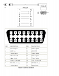
I compared the pinout for the Scangauge cable (top part of connector image) and the OBD II connector (bottom part of connector image) to determine which pins are being used. I narrowed it down to pins 4, 6, 7, 14, 16 of the OBD II connector. From the Scangauge pinout I matched those up to pins 1, 2, 6, 3, 8 of the RJ-45 connector.
Then I took an ethernet cable and determined the wire colors for the RJ-45 pins using a TIA/EIA 568B wired cable. (There is a 568A wiring spec but they are not ac common as the B spec. Regardless, check your cable type. It should be printed along the length of the cable.)
Here are the ethernet wire colors and pin number aligned with the OBD II pin numbers. (I didn't record the wire colors.)
Ethernet (pin) ---------- OBD II (pin)
White/Orange (1) ------ (4)
Orange (2) ------------- (6)
White/Green (3) ------- (14)
Green (6) -------------- (7)
Brown (8) -------------- (16)
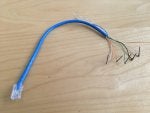
(This part is optional if you trust me.) Next I built a test rig (see attached image) to confirm the wiring before I pulled the tuck OBD II connector apart. I cut a short piece of ethernet cable and soldered nails to wires 1, 2, 6, 3, 8. Be sure to use nails that are approximately the same size as the OBD II connector pins. After inserting the nails into the proper connector holes I plugged the Scangauge in and ran some tests. Everything worked fine.
Next I pulled out the OBD II connector and used a pin removal tool to extract pins 4, 6, 7, 14, 16. Then I soldered the corresponding wire from a short piece of ethernet cable with an RJ-45 connector on the other end. (This is critical because otherwise you would have to crimp an RJ-45 on the stub. Too hard.) When you are soldering you must be very careful to keep everything small enough for the pin to fit back into the OBD II connector.
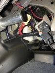
Once everything was all back together, I used an RJ-45 to RJ-45 coupler (ethernet coupler) and an ethernet cable (568B spec) to connect my Scangauge. I have been running it like this for over a year without any issue. (See attached image. Red cable is hardwired. Couple is beige and ethernet cable to Scangauge is black.)
Even though the factory OBD II connector is open, I cannot guarantee that other devices will work correctly with the Scangauge connected at the same time. I would also caution you to disconnect the hardwired Scangauge any time a tune or update may be flashed to your vehicle by you or another technician.