
Edit - here is a good thread on connectors:
2010 Ford Connector catalog is attached.
.
Link to the 2023 Ford Connector catalog:
.
NOTE: For the most part, the connector PART NUMBERS will apply to '03 and '04 model years also. I do not know if the Wiring Manual connector numbers do or not.
The PCM connectors, FICM connectors, and all of the common sensor and actuator connectors will work on ANY model year. I just "hedged" a little with the thread title, expecting to get even more detailed as time goes by.
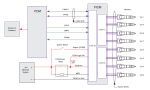
Connector C1282 provides critical power to the FICM and multiple critical sensors. Shorts in this connector (and the wiring to and from the connectors) have resulted in lack of injectors firing and subsequent no-start, and even a no-start condition from low or loss of PCM Power (short in fuse 22 circuit).
Recognition to @xstroker for giving me the "push" to start this (have been wanting to do it for some time now). I have this in his thread in the ELECTRONICS sub forum, but thought it would be good to post here to get some more views and hopefully get some of the gaps filled in.
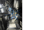
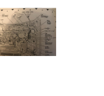
Mid harness connector locations:
.
.
2010 Ford Connector catalog is attached.
.
Link to the 2023 Ford Connector catalog:
.
| Connector part numbers: Primarily 2005 to 2007 model years |
NOTE: For the most part, the connector PART NUMBERS will apply to '03 and '04 model years also. I do not know if the Wiring Manual connector numbers do or not.
The PCM connectors, FICM connectors, and all of the common sensor and actuator connectors will work on ANY model year. I just "hedged" a little with the thread title, expecting to get even more detailed as time goes by.
Connector part numbers links | |
2005 to 2007 model years, but for the most part they are applicable to 03-04 model years also. | |
Description (Main Engine Harness): | Part # | Electrical Manual # |
| PCM X1 connector, To Engine, left connector | 2L1T-14A464-SD-028 Ford, 6-1438082-1 Tyco | C-1381A, 46 pin, Key A |
| Dual Processor Mod - Ford Truck Enthusiasts Forums | 2L1T-14A464-SD - NTI - The Connector People | |
| PCM X2 connector, To Engine, center connector | 2L1T-14A464-TD-017 Ford, 3-1438082-9 Tyco | C-1381C, 46 pin, Key B |
| 2L1T-14A464-TD - NTI - The Connector People | ||
| PCM X3 connector, To Transmission, right connector | 2L1T-14A464-UC-011 Ford, 1-1438083-5 Tyco | C-1381B, 30 pin, Key A |
| 2L1T-14A464-UC - NTI - The Connector People | ||
FICM X3 connector from PCM (Alliant Power part) | AP0018 without wires, AP0031 with wire pigtails | C-1388C |
Description (FICM - Injector Harness), Ford does not sell these | Part # | Electrical Manual # |
| C1388A (X-1, Inj 1,4,6,7). This is the end plug | AP0020 (without wires), AP0033 (with wire pigtails) | C-1388A |
| C1388B (X-2, Inj 2,3,5,8). This is the middle plug | AP0019 (without wires) or AP0032 (with wire pigtails) | C-1388B |
| Injector connector, harness side | AP0030 | 8 separate numbers |
| Injector Wire Harness Connector For Powerstroke - Prosource Diesel | Injector Connector Plug G2.8 For 03-10 6.0L Powerstroke | Prosource | Alliant Injector Harness Connector AP0030 |
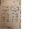
| Description (Instrument Cluster, HEC connectors), Ford does not sell these | Part # | Electrical Manual # |
| c220a, left plug, 26 pin | WPT-1161 or AU2Z-14S411-BCA | C220a |
| c220b, right plug, 26 pin | WPT-1391 or EU2Z-14S411-KA | C220b |
Description (Sensors, etc) | Part # | Electrical Manual # |
| ICP | 5C3Z-12224-A AU2Z-14S411-LB | C-1244 |
| EBP | 5C3Z-12224-A AU2Z-14S411-LB | C-1271 |
| MAP | 3U2Z-14S411-EXC was WPT-1218 | C-1087 |
| EGR Valve | 5C3Z-14A411-A, WPT-359 | C-1389 |
| EGR Throttle Plate - model year specific | C- | |
| MAF - model year specific, all but some '05's | 1U2Z-14S411-AY, was WPT-102 | C-128 |
| IAT1 - model year specific, '05 only | 3U2Z-14S411-JZA, WPT322 (was WPT420) Standard Motors S1080 | C-129 |
| IAT2 - Ford does not sell this | AP0056, Alliant Power | C-1236 |
| EOT - Ford does not sell this | AP0056, Alliant Power | C-104 |
| ECT - Ford does not sell this | AP0056, Alliant Power | C-1064 |
| IPR | 6E7Z-12A690-DA | C-1360 |
| VGT | 6E7Z-12A690-DA | C-1390 |
| CMP | 3U2Z-14S411-JCA, WPT-1271 | C-1275 |
| CKP | 3U2Z-14S411-CGC, WPT-359 | C-101 |
| Fan Clutch | 1U2Z-14S411-AKB, WPT-1136 | C-1158 |
| Oil Pressure Switch, EOP From the Instrument Cluster, NOT the PCM | 3U2Z-14S411-MHA, WPT439 Standard Brand S940 | C-103 |
| GPCM , both Black and Green | 4C3Z-12B568-AA | C-1273b, black C-1273a, green |
| BARO 2003 - Early2004 | 3U2Z-14S411-EZAA Standard Motor S805 (Rock Auto) | C-2256 |
| BARO Late 04 -2007 | 1U2J-14B475-AEA WPT-169 | C-2256 |
| APP (Accelerator Pedal) | 1U2Z-14S411-BRD, WPT1295 | C-2040 |
| Adjustable Accelerator Pedal Connector | C-2089 | |
| Adjustable Accelerator Pedal Motor Connector | C-2003 | |
| ESOF (4WD) Solenoids | C-1247 | |
| Alternator Connector | 1U2Z-14S411-TA, WPT-118 | C-102a |
| Heater Blower Motor Resistor Connector, NON EATC | 3U2Z-14S411-LXB (unconfirmed) WPT-1325 (unconfirmed) Possibly E7TZ-19A706-A | C-1032 |
| Heater Blower Motor Connector, NON EATC | C-1031 | |
| Heater Blower Mid Harness Connector, NON EATC | C-1019 | |
| A/C Dual Pressure Switch Mid Harness Connector | C-1298 | |
| A/C Dual Pressure Switch Connector | C-1062 | |
| A/C Compressor Cycling Switch | C-1081 | |
| A/C Clutch Relay Connector At BJB | C-1008 | |
| A/C Clutch Field Coil | C-100 | |
| A/C Clutch Field Coil Mid Harness Connector | C-1282 | |
| Vacuum Pump Motor Connector | C-1119 | |
| Ambient Air Temperature Sensor Connector | C-132 | |
| Ambient Light Sensor, Sun Load Sensor | WPT214 | C-286 |
| Temperature Blend Door Actuator Connector | C-289 | |
| DLC connector (Data Link Connector or OBDII Port) | C-251 | |
| ABS Module | C-135 | |
| Brake Fluid Reservoir Switch | 3U2Z-14S411-EXB (unconfirmed) 3U2Z-14S411-HRA (unconfirmed) | C-124 |
| Brake Pressure Switch Connector | 3U2Z-14S411-JZA unconfirmed S1080 unconfirmed | C-1025 |
| Brake Pedal Position Switch Connector | C-278 | |
| Brake Pedal Position Switch Mid Harness Connector | C-146, 17 pin | |
| Parking Brake Switch Mid Harness Connector | C-145, 17 pin | |
| 4WD Control Module Mid Harness Connector | C-145 | |
| To Mid Harness Air Bag Sliding Contact | C-145, C-146 | |
| Oil Pressure Switch Mid Harness Connector | C-145 | |
| Air Filter Filter Minder, Mid Harness Connector | C-145 | |
| Air Filter Filter Minder, to HEC | C-1210 | |
| CAN (PCM) to HEC Connector, Instrument Cluster | C-220b | |
| CAN (PCM) to TBC | C-2142b | |
| PCM to CJB (Fuel Pump Relay) | C-270f | |
| PCM to Starter Relay | C-270f | |
| VPower to CJB | C-270h | |
| Third PCM to CJB connector | C-270g | |
| WIF Sensor Pigtail | WPT-1116 | C-1010, 16 pin, mid harness, then C-1386 to C-1080 |
| Fuel Pump Connector | 6C3Z-9F759-A | C-1010, mid harness, then C-1386 to C-1392 |
| Inlet Air Restriction Sensor Connector, from HEC | WPT-692 | C-1210 |
| Transfer Case Shift Motor Harness Connector | C-350a | |
| Transfer Case High-to-Low, Low-to-High Connector | WPT-856 (unconfirmed) | C-350b |
| PCM to transmission (large "bolted" connector) | C-1385 | |
| Transmission Speed Sensor Assembly Connector | C-1387 | |
| Transmission Output Shaft Speed Sensor Connector | C-1107 | |
| Windshield Wiper Motor Connector | 5U2Z-14S411-KC (unconfirmed) was 3L3Z-14489-BA | C125 |
| Windshield Washer Motor Connector | C137 | |
| 12 pin mid harness connectors Male: 12A581 Female: 12B637, meaning this one is part of the engine wiring harness | Possible (unconfirmed): 4C3Z-14A594-BA 5C3Z-14A594-E | C-110 C-1282 (see below) |
| CET1229F | CET1229M | C1282 |
| 12 pin mid harness connectors male: 14405 female: 12A581 | C-140 | |
| 16 pin mid harness connectors | C-1010 | |
| 17 pin mid harness connectors | C-145 C-146 |
Connector C1282 provides critical power to the FICM and multiple critical sensors. Shorts in this connector (and the wiring to and from the connectors) have resulted in lack of injectors firing and subsequent no-start, and even a no-start condition from low or loss of PCM Power (short in fuse 22 circuit).
| C1282: Pin positions and wires: 1) BK/PK (Black with Pink stripe) - FICM ground to G101, from FICM C1388c Pins 1,2,3,22,26 to G101 2) GY/WH (Gray w/ White stripe) - W/ EATC from BJB A/C Clutch relay C1008 Pin 5 to A/C Clutch Field Coil C100 Pin 1 3) - (Mine is Empty, other model years looks like a BK/VT (Black with Violet stripe) - 4) Female connector empty, into male connector only OG/LB (Orange with Light Blue stripe) - 5) Female connector empty, into male connector only LG/VT (Light Green with Violet stripe) - 6) WH/BK (White with Black stripe) - Logic Power from BJB F1.15 to FICM C1388c Pin 8 7) BK (Black) - A/C Clutch Coil C100 Pin 2 to G100 and G202 (numerous grounds on this circuit) 8) RD/YE (Red w/ Yellow stripe) - Ground wire from FICM C1388c Pin 27 to activate BJB FICM relay C1235 Pin 2 9) VT/OG (violet with Orange stripe) - 12V power from ignition switch C250 Pin 1 "Run & Start", through C145 Pin 1, to FICM C1388c Pin 7 10) RD (Red) - 12V Power from CJB F2.22, C270h Pin 5 to EGR C1389 Pin E, IPR C1360 Pin A, GPCM C1273b Pin 9, Fan Clutch C1158 Pin 5 11) BN/OG (Brown with Orange stripe) - Oil pressure switch C-103 Pin 1 to HEC C220b Pin 15 through C145 Pin 30 12) DG/LG (Dark Green with Light Green stripe) - FICM VPower from FICM relay C1235 Pin 3 to FICM C1388c Pins 4,23,24,25 |
Recognition to @xstroker for giving me the "push" to start this (have been wanting to do it for some time now). I have this in his thread in the ELECTRONICS sub forum, but thought it would be good to post here to get some more views and hopefully get some of the gaps filled in.
Mid harness connector locations:
.
.