Ford Powerstroke Diesel Forum banner
Status
Not open for further replies.

Circuit diagram for PCM/IDM and 42-pin connector?

55K views 3 replies 3 participants last post by  tellenb0  
#1 ·
Can anyone help me identify the pink/black wire that was shorting on the left valve cover of my 2003 7.3L F250? The wire is in the harness from the PCM/IDM that attaches to the 42-pin connector. I have not found complete circuit diagrams or pin-out schematics in the Ford workshop manual, or the power control and emissions diagnostics manual.

Does Ford publish full wiring diagrams for the engine control systems? Is the International diagnostic manual for this engine (EGES-125-1) a better source for this information?

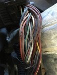
The short caused an intermittent misfire, especially in humid conditions, although the injector buzz test was normal. I repaired the damaged wire by soldiering in a short length of new wire and covered it with heat shrink tubing. The other scuffed wires (no copper showing) were wrapped with vinyl tape then the whole bundle was wrapped with a self adhesive silicone tape to pad the harness and seal out moisture. Finished with red vinyl tape to match the factory stripes. Lol. So far, so good.
 

Attachments

#2 ·
Here's what I have. The Powertrain Control System doc may have what you are looking for. The two large documents should, as well. ...if you can find it. :)
 

Attachments

Save
#3 ·
I have this;


2002 Superduty Connector C110 Pin-Out Information
Pin Wire Color Circuit Number Description Action To From
1 - - - - - -
2 Tan 555 #1 Injector Ground Ground #1 Injector IDM Pin 6
3 Dark Green 556 #2 Injector Ground Ground #2 Injector IDM Pin 22
4 Tan/Red 561 #7 Injector Ground Ground #7 Injector IDM Pin 20
5 Brown/Yellow 557 #3 Injector Ground Ground #3 Injector IDM Pin 21
6 Brown/Light Blue 558 #4 Injector Ground Ground #4 Injector IDM Pin 7
7 Tan/Black 559 #5 Injector Ground Ground #5 Injector IDM Pin 8
8 Light Green/Orange 560 #6 Injector Ground Ground #6 Injector IDM Pin 19
9 - - - - - -
10 Light Blue 562 #8 Injector Ground Ground #8 injector IDM Pin 9
11 Pink/Black 878 Drivers Side Injector Power Power UVCH IDM Pin 23
12 Orange 1087 Passenger Side Injector Power Power UVCH IDM Pin 24
13 Violet/Orange 1086 GPR/GPCM On Signal from PCM Control Signal Ground GPR # 86/ GPCM #8 PCM Pin 101
14 Red/Yellow 1291 Air Charge Temp Sensor Signal Resistance to Pin 19 ACT # 2 PCM Pin 62
15 N/A Shield 48 IDM Shield Ground Shield Ground Injector Harness Shield IDM Pin 18
16 Black/White 570 Exhaust Back Pressure Regulator Ground EBP Regulator #2 Ground 101
17 Light Green/Red 354 Engine Oil Temperature Signal Resistance to Pin 19 EOT # 1 PCM Pin 38
18 - - Coolant Temp Sensor Signal (Manual Trucks) - ECT # 2 PCM Pin 37
19 Grey/Red 359 Engine Oil Temperature Signal Return Ground EOT # 2 PCM Pin 91
20 Violet/Light Blue 553 Exhaust Back Pressure Sensor monitor (0-5 volt) Positive EBP # 2 PCM Pin 30
21 Brown/White 351 5 Volt VREF (CPS, MAP, EBPS, ICPS) Positive EBPS #1, MAP #1, CPS #2, ICP #1 PCM Pin 90
22 Dark Blue/Light Green 812 Injection Control Pressure Sensor Monitor (0-5 volt) Positive ICP #2 PCM Pin 87
23 Grey/Yellow 318 Exhaust Pressure Regulator Control (12V) Positive EPR # 1 PCM Pin 42
24 Red 361 12 Volt Power : (MIAH, IPR, GPR/GPCM) Positive Splice 1001 CJB # 5 (Fuse #22)
25 Yellow/Red 552 Injection Pressure Regulator Control Signal Ground IPR # 2 PCM Pin 83
26 Violet 462 Manifold Intake Air Heater Control Signal Ground MIAH Relay # 86 PCM Pin 98
27 - - - - - -
28 White/Red 1275 Waste Gate Solenoid Control Ground WGS # 1 PCM Pin 47
29 Yellow/Red 45 Coolant Temperature Sensor Resistance to Pin 31 Coolant Temp Sensor # 2 Instrumet Cluster # 6
30 White/Red 31 Oil Pressure Switch Ground Engine Oil Pressure Switch #1 Instrument Cluster # 8
31 Red/White 39 Coolant Temperature Sensor Signal Resistance to Pin 29 Coolant Temp Sensor # 1 Instrument Cluster Pin 7
32 Red/Yellow 3996 Manifold Air Intake Heater Relay Monitor MIAH Relay #87 PCM Pin 3
33 Light Blue 796 CPS Return Signal Return (12V Hall Effect) Positive CPS # 3 PCM Pin 65
34 - - - - - -
35 Red/Light Green 16 Waste GateSolenoid, Fuel Heater Power (12 Volt) Positive WGS # 2, Fuel Heater # 1 IGN Switch
36 White/Yellow 1183 Alternator Charge Indicator Positive Instrument Cluster # 12 Generator #1
37 Grey/Red 1280 Water In Fuel Sensor Signal Ground WIF Sensor #2 PCM Pin 36
38 - - - - - -
39 Dark Green 795 Cam Position Sensor Ground ? CPS # 1 PCM Pin 21
40 - - - - - -
41 White/Light Green 1277 Glow Plug Relay Monitor Positive GPR # 87/ GPCM #9 PCM Pin 8
42 - - - - - -
 
#4 ·
I think the affected wire is #11, driver's side injector power. Will confirm the pin position when I have time. It sounded like one bank of cylinders had dropped out when the problem was fully manifested. Other times, it was a more limited misfire, probably depending on the amount of arcing to ground. Thank you!
 
Status
Not open for further replies.
You have insufficient privileges to reply here.