Ford Powerstroke Diesel Forum banner

6.0 battery cables so huge for what reason

18K views 41 replies 17 participants last post by  Busterdiesel  
#1 ·
I work with semi trucks quite a bit. I hardly see 1/0 Guage wire for batteries, what would happen if I swapped the cable out with 1 Guage wire? I can't seem to find the terminals I want to make it look good without exposing the wire? I tried junkyards but no luck.
 
#2 ·
I would try NAPA for the cable ends or a welding supply house for the cable. I am not an electrical expert, but I think a ! gauge cable would be quite sufficient even for extended cranking times. Welcome, I'm a newby too! Lots of good info and helpful people here.
 
#4 · (Edited)
i would not dare going smaller than original, why risk it? The OEM for a 6.0 is 2/0 i believe. but my 1/0 was oversized and a quality supplier, so i was satisfied.
i just re did all of mine, aside from the starter cable. and i added a 4ga to the alt.
after all my research, I used tinned OFC cable and search amazon for tinned "marine grade" lug ends, and dual wall adhesive lined heat shrik. "marine grade" is a common search term. and then a wire loom of your choosing

for non diy, most people like Custom Battery Cables - Best Quality Copper Replacement | USA Made
 
#6 ·
2/0 would be fine -- 1/0 is smaller -- #1 is smaller still -- see how this works, gotta stay on the left side of Zero for battery cables ?
1/0 welder cable will carry more "power" than standard battery cable, but is more expensive -- surface area of the wire strands and all that

"I work with semi trucks quite a bit "
2/0 is pretty common to connect each battery, up to some that use 4/0 for the lead to the starter
 
owns 2006 Ford F250 Lariat FX4
  • Like
Reactions: jrsavoie and bismic
#7 ·
I work with semi trucks quite a bit. I hardly see 1/0 Guage wire for batteries.
I don't work on semi trucks, but many of the modern engines I work on are 24 Volt Crank and charge, but everything else is 12 Volts. If the semis you're working on are 24V crank, yes the cables can be half the size for the same load. Another consideration is the length of the run from the batteries to the starter. In a semi the batteries are usually only 3 or 4 feet from the starter. In a Super Duty, the driver side battery is almost 15 feet of cable-run away.

I wouldn't change the gauge unless you reeeealy know what you're doing.
 
#8 ·
Heavier gauge is better for 12 volt systems. I purchased some 4/0 for the battery cables in my Travel Trailer and the run is only 5’ because otherwise you loose way to much with the smaller cables and they tend to heat up quite a bit more. These cables are for my battery to inverter connection. Any medium to large voltage drop isn’t good and with the smaller cable and the longer cable run the more drop you will see. The 15’ run from the drivers side should actually be a larger gauge than the passenger side because of distance traveled but manufacturers use what’s cheapest that will do the job, sometimes just barely. I wouldn’t go smaller but I would consider going larger. Price of wire these days, as with most things, is very high. I purchased mine when President Trump was in office so my cost was waaaaaaay lower than they cost now. Thanks Brandon.
 
  • Like
Reactions: jrsavoie and 734me2
#9 ·
That's doing some reaching, right there...lol.
 
  • Like
Reactions: 2001 f350 cc 4x4
#10 ·
If I run new cables can i connect the drivers side battery straight to the alternator (with a heavy in-line fuse of course) instead of running the drivers pos to the passenger pos and then to the alternator. My plan is to run a new 2/0 from each battery pos to the alternator with in-line fuses while leaving the original alternator to passenger battery. The drivers pos to passenger pos wire is gone. Will the current flow through the alternator to the starter when demanded? I figure it will because I believe the alternator has a delay before it starts to charge.
Thank you!
 
#22 ·
During my endeavors, the truck will let you know that this isn't a good idea. I've one large cable, that runs from the drivers side to the passengers positive clamp, and the clamp is like what a semi would have on it or similar.
I've changed out the grounds on the passenger side, under the fender to the frame. I've cleaned all the contacts to the grounds, that I can find. I've plans to connect the neg of the drivers side to the frame, and then from there go to the eng. and yes, I got this from watching someone on You tube. But, I've been trying to figure out how to make my truck run correctly, since I bought it. Plus, I put in two new interstate batteries, and a 250 amp alternator. So far, when I was running it, all the scope is calling for is new glow plugs. I removed the under skirting of the fenders, but still trying to get the wire looms to come off. These seem to be original, since they fall apart soon as you touch them. Still learning about the Tan Man. TT04, 6/7/2022
 
#11 ·
Laying heavy, large-capacity cables across the top of my engine is not one of those things I would conceive of doing.
I would seriously rethink this if I were you.
 
#12 ·
Yeah, that is asking for a engine bay fire right there
 
owns 2006 Ford F250 Lariat FX4
  • Wow
Reactions: jrsavoie
#15 ·
For me, not really.

Have you ever seen anything like this in the history of vehicles? I'll give you ten points for unique.

I'll play a little.

One of my concerns would be the electrical field developed around the cables, which would be at maximum during engine start. The factory harness has shielding to deal with interference from its neighbors and the field around the alternator. Some of its neighbors are also the injector wiring.

A slightly funky alternator diode that allows for A/C ripple has been known to cause issues, such as the transmission operating improperly. And that's the factory alternator with factory wiring. You are putting large cables with both inductance and capacitance over all these sensors and harnesses, and one big humping field during starter engagement. That's one hell of a flux capacitor.

Ford could have put the battery to battery cable near the operational harnesses. They don't. They put it far away from the harnesses.

And since I'm playing, one video to watch.


And then it's more colorful correction.


The system may be shielded enough. The alternator problem child was a 7.3L Powerstroke, and ham radio operators have noted the 6.0L is better shielded than the 7.3L. Give it a go.
 
#16 ·
I've been schooled! Hydro: thanks for the gauge clarification, and well put. bismic: I hadn't thought of the processor voltage, at all. Now that I have considered the glow plugs and starter draw, it's amazing there is enough left to run the processor. TooMany Toys: You "play" well! Good points on wire routing with respect to other harnesses. And the tip on a "funky diode" could cause transmission problems, I won't forget. I apologize for the misinformation and will think things out, before popping off. Thank you all for educating me! "Lots of good info and helpful people here"
 
#17 ·
The "computers" run from the driver side battery -- the smaller positive crossover ensures that the driver side battery does not lose too much power during a crank

Over sizing the driver side cables creates a low power situation for the electronics -- some design thought was put into that system to keep the electronics powered

That means the passenger battery is the work horse of the system -- if you want the batteries to last longer, it would be a good idea to swap sides occasionally to balance out the wear
 
owns 2006 Ford F250 Lariat FX4
#21 · (Edited)
fascinating does this mean i should not be replacing the cross + wire that runs across the top of the rad with 0 gauge?

The problem with the driver's side battery powering the electronics is the factory setup has the primary 8ga negative to the body tub ground plane off the passenger battery. Unless you have a dual..ETC
you are honestly a national treasure dude
 
#18 · (Edited)
The problem with the driver's side battery powering the electronics is the factory setup has the primary 8ga negative to the body tub ground plane off the passenger battery. Unless you have a dual alternator setup.

Excluding the resistance of the cables:

The negative from the driver's side goes through 4 bolt-up connections of series resistance to get to the ground plane; two positive connections of series resistance to the CJB. And when engaging the starter, the electrical flow through the 12ga bonding cables is not going to the ground plane; it's heading to the hungry starter.

The passenger negative has two bolt-ups to the ground plane, while the positive has three bolt-up connections to the CJB.

I'd agree about the stock setup if both batteries had the 8ga negative lead to the body tub. This is why I came up with adding an 8ga negative cable from the driver's negative side to the FICM/PCM/Body Tub connection. Many people have reported the same results I have, about a 0.5v improvement off the OBD2 readings.

Swapping side to side gets both batteries to "wear down" equally fast.


I think in terms of election flow, not current flow.

Image


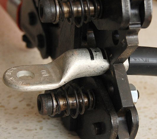
The layout. Ignore my dashed cable addition.

Image


During starter engagement, electron flow (using the generic "current" term) goes from the body tub to the frame. All electron flow for the electronics is coming from the passenger battery through the 8ga cable at over 51 amps. Not the 19-20 amps that the engine electronics use when cold. So it's also feeding the starter through the cables.

Image


Once the engine is running and the batteries are fully charged, the 8ga passenger negative cable and the two 12ga "bonding" cables share the alternator output as parallel circuits feeding the engine electronics. Until a high load is demanded, then the two lower resistance cables handle most of the flow. And that shows the importance of the 12ga bonding cable under the passenger foot area to the frame.

The three cable connections act as any parallel circuit would; amp flow is based on resistance. The resistance values are for the cables. The connection resistance is variable from vehicle to vehicle, depending on the cleanliness of the connections.

Image


All current flow measurements are documented in my video about this, and each situation repeated a minimum of three measurements. And I was damn surprised that the "bonding cables" flow as much as they do. Even more surprised when I saw the direction of flow changing.

But the positive feed to the CJB is 4ga. The only "feed" for the negative side is the 8ga cable off the passenger battery (single alternator) in the Ford diagrams.

Overall, IMO, this factory design accommodates the assembly line and gas engine setups, but it was not optimized for the diesel two battery system.
 
#19 ·
Addendum.

If Ford (or any of us) wanted to use the driver's battery as the main supply to the electronics, an 8ga driver's negative-to-body tub connection should be made, and the 8ga negative connection off the passenger battery removed. That's a valid design. Not optimal for the batteries, but with everything, you chose your priorities.
 
owns 2003 Ford F-350 Lariet
  • Like
Reactions: Hydro
#20 ·
Since, I'm a fabricator to a point, I was given some cables, not sure on the guage, but they were really nice with a lot of copper. So, I used copper tubing, and cleaned the ends, cut an approx size that would work for us. pounded one end flat, and drilled the hole for the bolt to go through, and then soldered the battery cable into the end of the tube. I let it cure about a day, then placed it on the battery post. Or, I've used them for a ground cable also. I did put the black electric wire around them, just in case, but it depends on what it was for. They seem to work pretty good. TT04, 6/6/2022
 
#25 ·

He builds cables the size and manner I suggested in a forum about 6-7 years ago, except they are not tinned. Marine Grade is what I use because they are tinned, although the insulation has a lower temp range.

Stock:
Crossover Positive - 2ga
Starter Positive - 2/0ga
Battery Negative (Both) - 1/0ga
Negative to Body Tub - 8ga.
Not indicated in the Factory Diagrams, the two 12ga braided bonding cables are part of the Body Tub connection for the ground plain.
 
#27 ·

This is a good company that makes cables to your specs which are marine cables.
 
#31 ·
Waytek is an excellent source. When I had my test facility, many things were purchased from them.
 
#33 · (Edited)
They don't, never have. But it is a great supplier of many parts.

But if I'm going to get marine cable, it will be from a store that supplies to the marine industry. The cable I always try to buy is Ancor.

Belden also makes tinned wire, which I usually get from Newark, also a great supplier of parts.

 
owns 2003 Ford F-350 Lariet
#36 ·
You are having trouble finding 1/0 battery terminals for a Group 65 battery?

I ordered some battery terminals for a car off of Amazon, and was so disappointed with the quality of what I received, I disposed of the ones off Amazon and cleaned then reused the old ones.

If someone has an example of what they have used other than an OEM replacement Lug. Might help him. Personally am not afraid of crimping; its not that hard cutting off a little bit of wire and adding a lug, but I am afraid of spending money on a replacement lug to have it come in and be useless because the replacement is only as thick as sheet metal.
 
#37 ·
for terminals i used these which i think most on here use
Amazon.com: Ampper Military Spec Battery Terminal End, Top Post Battery Terminal Set for Marine Car Boat RV and Vehicles (1 Pair) : Automotive

for the lugs i use these in varying sizes for the wire and connection size. "marine grade" is the normal key word for the tinned stuff on amazon
TKDMR 10pcs 1/0 Awg-3/8" Ring Marine Grade Copper Wire Lugs,with 3:1 Heat Shrink Tubing,UL Battery Cable Ends,Heavy Duty Cable Lugs,Tinned Copper Eyelets,Tubular Ring Terminals: Amazon.com: Industrial & Scientific

i also broke down and got a hydraulic crimper. so many less headaches, safer and more secure. and it pushed me into making better cables for my older cars too
Industrial Hydraulic Cable Lug Crimper 16TON 9 AWG to 600 MCM Electrical Terminal Cable Wire Tool Kit Includes 13 pairs of Die Sets - - Amazon.com
 
#39 ·
Every lug supplier has different specs. The wall thickness varies from company to company, as well as style, and so do the dimensions of the crimping dies, square or hexagonal.

How the wall thickness can vary.


For the cable setups I've made and the ones I will make for a video, I use products from Quick Cable. But I also use FTZ lugs, depending on the situation. Sometimes their lugs are a better fit for the application. If you've followed any of my videos on electrical, it's not a subject I take lightly. I can't pull any images as I'm reloading my MAC dedicated to the Powerstroke for about the 50th time.


This is one of the best sites for the subject; I have two of the crimpers he mentions; FTZ 94284, AMP Rota-Crimp 600850 (which would be insane to buy today, it's triple the price), and one from Ancor.


As in their site, I've tried the hydraulic crimpers and don't care for them. I've not tried the new battery-powered crimpers used in solar applications.

This video says they have a good crimp; they don't, but it's close. It should look like solid copper.